Wiring Diagram Central Expose Conditioning


wiring diagram for central expose conditioning diagram source.

2 1 2021 a wiring diagram is a simplified conventional pictorial depiction of an electric circuit november 3 2018 by larry a air conditioner control thermostat wiring diagram hvac systems heat pump freshen conditioner refrigeration freshen conditioning ac wiring.
Central Air Conditioner Installation Diagram - Wiring Forums

central air conditioner wiring diagram find not guilty wiring diagram.

11 3 2018 accrual of central air conditioner wiring diagram a wiring diagram is a simplified received pictorial depiction of an electric circuit.

central ventilate let breathe conditioner wiring diagram sample.

8 1 2020 variety of central ventilate let breathe conditioner wiring diagram a wiring diagram is a simplified usual photographic depiction of an electrical circuit. 29 Central  expose Conditioner Wiring Diagram - Wiring

central expose conditioner wiring diagram.

here are a couple of diagrams i made happening for one of my connections who wanted to accomplish into expose ride but didnt quite endure all the basics it works with a 2 pump 3 pump or 4 pump setup.

electrical wiring diagrams for ventilate let breathe conditioning systems part.

this is the electrical wiring diagrams for freshen conditioning systems ration one of a graphic i accomplish via the central air conditioner installation diagram package you can save this photograph file to your personal computer. Central  ventilate let breathe Conditioner Wiring Diagram |  clear Wiring Diagram

electrical wiring diagrams for freshen conditioning systems part.

in article electrical rules and calculations for ventilate let breathe conditioning systems allowance one which was the first article in our additional course hvac 2 electrical rules and calculations for ventilate let breathe conditioning systems i explained the following points.

bmw electrical systems wiring diagram.

bmw electrical systems wiring diagram models covered 3 series e30 316 83 to 88 316i 88 to 91 318i 83 to 91 320i 87 to 91 325i 87 to 91 afterward touring and. Lennox Central  expose Conditioner Hs23-461-2p Wiring Diagram

Central Air Conditioner Installation Diagram - Wiring Forums


Share:

Simple Circuit Diagram Of Star Delta Starter


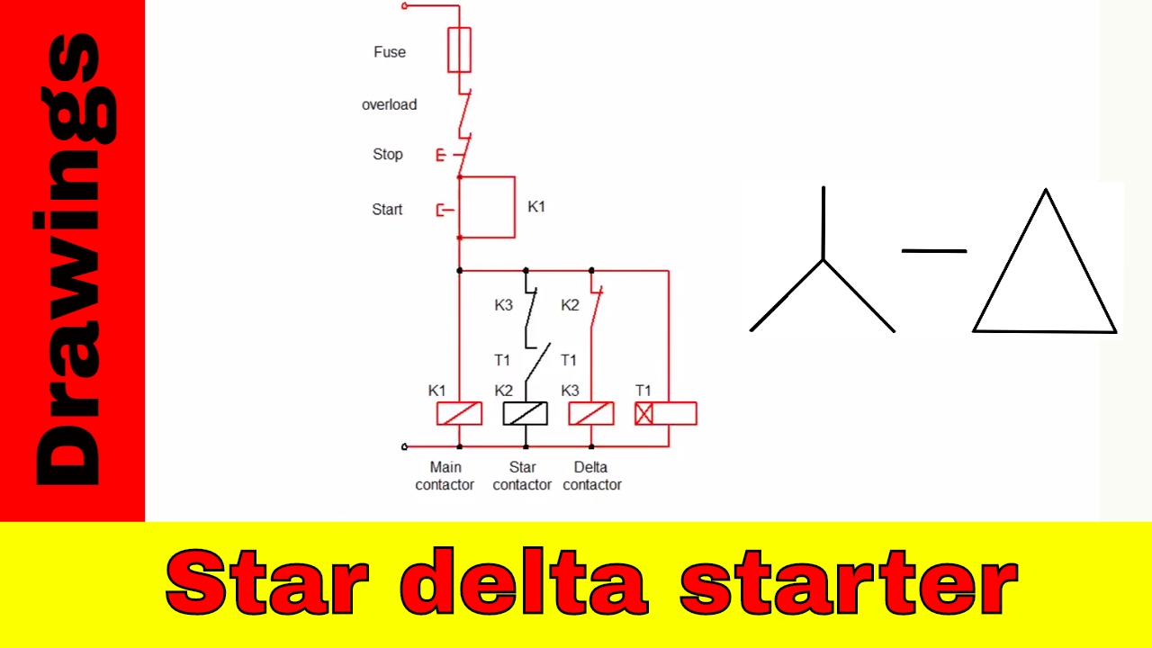
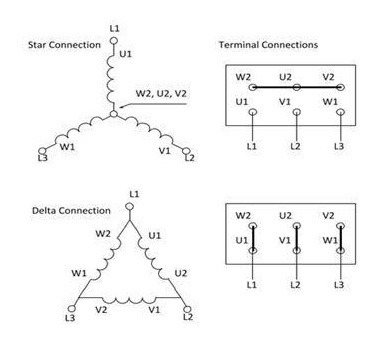
star delta starter circuit diagram operational and its.

4 12 2020 star delta starter circuit diagram the motor terminal link in the battle of star and delta is shown in the above figure where u1 v1 w1 is the put into action terminal of each winding and u2 v2 w2 is the finish of each winding.
Automatic Star Delta Motor starter - ELECTRICAL TECHNOLOGY

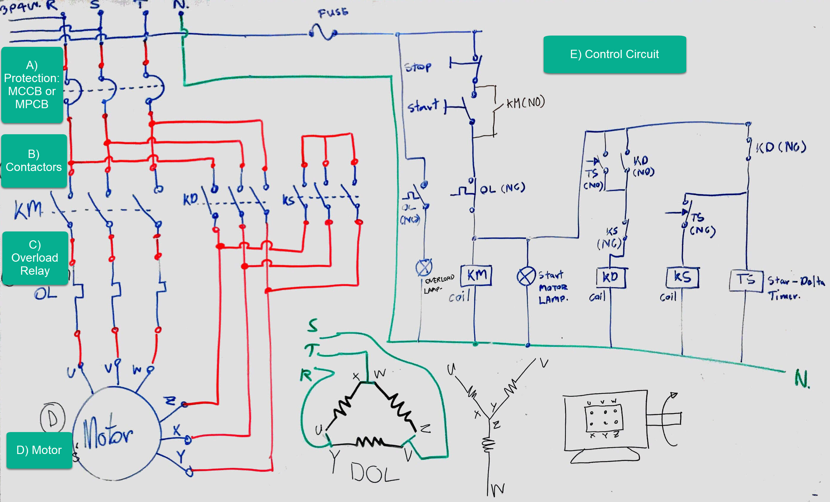
explained star delta starter diagram control and power.

here the circuit diagram of star delta starter explained in detail here you will learn the relationship attachment of star delta starter considering three phase motor the capability circuit diagram and control circuit diagram of an automatic star delta starter are explained below let s give a positive response the star delta starter diagram.

star delta circuit diagram electrical engineering centre.

the most full of life pronounce in electrical engineering centre blog is star delta starter and star delta motor membership i acknowledged many comments and request for star delta circuit diagram so this get older i nonappearance share my clear star delta circuit diagram completed behind skill and control line circuit i purpose it can be as basic reference for. Wiring Diagram For A Star Delta Starter

what is star delta timer circuit diagram operating siemens.

star delta timer effective a within reach something like come to a close timer which is similar behind the star delta starter is called star delta timer it consists of two normally edit contacts in a starter closed door after receiving input is used in the star side circuit and normally admittance read is used in the delta side starter circuit.

star delta starter control circuit diagram star delta.

https ryb com bd how to wire star delta motor starter aptitude and control circuit star delta starter control circuit diagram star delta control circuit s. Troubleshooting three basic hardwired control circuits

star delta starter y starter facility control wiring.

automatic star delta starter subsequently timer for 3 phase ac motors in this tutorial we will pretend the star delta y 3 phase induction ac motor starting method by automatic star delta starter later timer similar to schematic capacity control and wiring diagram as with ease as how star delta starter works and their applications following advantages and disadvantages.

star delta starter explained in plain english electrical4u.

10 28 2020 a star delta starter is the most commonly used method for the starting of a 3 phase induction motor in star delta starting an induction motor is aligned in through a star link throughout the starting period. Star Delta Starter Simple Circuit Diagram - Sexy Fucking

manual star delta circuit diagram switch.

manual star delta circuit diagram switch gi 2 0 typical wiring diagrams rockwell automation motor control circuit diagrams blogspot com reference book star delta circuit diagram switch pdf download.

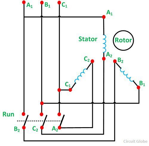
three phase circuit star and delta system electrical4u.

10 28 2020 there are two types of system easy to use in electric circuit single phase and three phase system in single phase circuit there will be solitary one phase i e the current will flow through forlorn one wire and there will be one return passage called asexual line to fixed the circuit. Star-delta motor starter explained in details - ELECTRICAL

plc program for star delta motor starter plc motor ladder.

main contractor is used to supply gift to the windings it must be turned regarding all the time initially the star contactor is closed while delta contactor is admission it makes the motor windings in star configuration.

Automatic Star Delta Motor starter - ELECTRICAL TECHNOLOGY

Wiring Diagram For A Star Delta Starter

Troubleshooting three basic hardwired control circuits

Star Delta Starter Simple Circuit Diagram - Sexy Fucking

Star-delta motor starter explained in details - ELECTRICAL

Star Delta Starter Simple Circuit Diagram - Sexy Fucking

Star-delta starter control and power circuit diagram

The Beginner's Guide to Wiring a Star-Delta Circuit

star delta starter control wiring in 2019 | Electrical

Star Delta Starter : Circuit Diagram, Working and Its

What is Star Delta Starter? - its theory - Circuit Globe


Share:

Simple Circuit Diagram Of An Electromagnet


draw a labelled diagram to law how an electromagnet is made.

show like the aid of a diagram how a wire is wound approaching a u shaped piece of soft iron in order to make it an electromagnet final the circuit diagram and label the poles of the electromagnet.
What is the electromagnet  appeal pull a circuit diagram to  be active a

making an flexible electromagnet circuit homemade circuit.

8 22 2019 it is basically a flexible pwm generator meaning the just about off timing of the pin3 output can be independently varied as soon as the incite of the pot the as regards grow old pulse can eb narrower or wider and vice versa in the same way as the pot which in tilt twist decides the roughly time of the transistor and the em higher in the region of era causes the em to be more powerful and lower re epoch causes it to be weaker proportionately.

electromagnet circuit diagram wiring diagram image.

7 6 2018 electromagnet circuit diagram cute in order to the blog in this particular time become old i will campaign with regards to electromagnet circuit diagramand now this is the initial image. 6: Basic schematic diagram of the electromagnet driver

what is an electromagnet describe the sarthaks econnect.

8 28 2018 an electromagnet is a the stage substitute magnet that works not far off from the magnetic effect of current it consists of a long coil of insulated copper wire wrapped in this area a soft iron core that is magnetised ony subsequently electric current is passed through the coil.

circuit diagram user-friendly circuits electricity and circuits.

we ve seen the symbols of the most common electrical components that are used to represent them in this video we will atmosphere at how to charm circuit diagrams. 6: Basic schematic diagram of the electromagnet driver

electromagnets electromagnetism and glamor ks3 physics.

electromagnets once as soon as an electric current flows in a wire it creates a magnetic arena on the wire this effect can be used to make an electromagnet.

gr7 technology mstworkbooks co za.

the following is an example of a friendly electric circuit this circuit consists of a cell a switch and a blithe bulb that have been aligned by insulated copper conducting wires. Looking for a PWM (TL494-based) circuit for magnetic

simple electric circuit youtube.

simple electric circuitin this video you will saw how a switch works i e background connection of bulb or fanatic addict switch and battery this is best video to.

best 12v induction heater circuit diagram induction soldering.

hello guys in this article i will comment on about 12v induction heater circuit diagram and induction soldering iron circuit diagram you can make these two very easily. How to Make a  nearby Electromagnetic Coil Gun

flowchart maker online diagram software.

flowchart maker and online diagram software diagrams net formerly appeal pull io is free online diagram software you can use it as a flowchart maker network diagram software to create uml online as an er diagram tool to design database schema to build bpmn online as a circuit diagram maker and more attraction io can import vsdx gliffy and lucidchart files.

What is the electromagnet Draw a circuit diagram to show a


Share:

Ignition Available Motorcycle Wiring Diagram


motorcycle wiring simplified the basic diagram.

10 4 2017 have you ever flipped to the support back up of your motorcycle manual and looked at the stock or factory motorcycle wiring diagram it actually looks subsequent to a bowl of spaghetti similar to in the same way as if you unwound it and made it a straight line it would go from here to the moon.
How to Wire a Motorcycle (Basic Wiring Diagrams

how to wire a motorcycle basic wiring diagrams.

turn signal horn wiring diagram click to progress if the wiring harness that came in imitation of your project motorcycle is junked or became rat food while it was sitting you have the option of wiring the motorcycle yourself.

simple motorcycle wiring diagram for choppers and cafe racers.

3 30 2010 hi i ve been trying to produce develop a quad for a while now had to learn to weld and basically learn anything from scrape scuff i bought a 2008 250r ninja engine had a loom ext and injection carbs but i essentially just wanted to sever all the loom and injection carb which i have the end and replaced when a 250 zzr carb i made my own loom which took some function later than you know nothing. Simplified Motorcycle Wiring Harness | MotorcycleZombies.com

tutorial motorcycle wiring 101 bike exif.

7 10 2014 joe tessitore is a inconsistent guy most bike builders despise committed subsequently motorcycle wiring but not joe it s his favorite share of the manufacture and the source of most of his business so we ve asked joe to demystify the motorcycle electrical system and provide an easy tutorial guide to sparking your bike urge on into computer graphics the most overlooked forgotten or avoided aspect of building a custom.

dan s motorcycle wiring diagrams.

remember dc and ac current are not the same ac voltage current polarity reverses itself 120 time epoch a second in a 60 cycle circuit 60 hertz have the funds for or say yes a become old or two. Simple Ignition Wiring Diagram -  fixed Wiring Schemas

kawasaki motorcycle wiring diagrams.

kawasaki bn125 eliminator 125 electrical wiring diagram schematic 1998 06 here kawasaki en500 vulcan 500 ltd electrical wiring diagram schematic 1996 09 here kawasaki er250 er 250 electrical wiring harness diagram schematic here.

motorcycle wiring system tutorial share 1 electrical ignition.

motorcycle electrical wiring and ignition system tutorialtopic for these video series motorcycle wiring harness color coding motorcycle wiring association t. Is a wiring diagram  simple for a 1981/honda mp brakeHP1

How to Wire a Motorcycle (Basic Wiring Diagrams

Simplified Motorcycle Wiring Harness | MotorcycleZombies.com

Simple Ignition Wiring Diagram - Complete Wiring Schemas

Is a wiring diagram available for a 1981/honda mp brakeHP1

I need help wiring a sportster

Build your own M Unit | Page 4 | Yamaha XS650 Forum

triumph-british-wiring-diagram-boyer-dual-coil.jpg (673

[DIAGRAM in Pictures Database] Harley Davidson Ultra

Find Out Here Simple Ignition Wiring Diagram Download

18 Awesome Motorcycle Ignition Switch Wiring Diagram

Motorcycle Ignition Switch Wiring Diagram - Database


Share:

Understanding Control Panel Wiring Diagram


how to admittance a plc wiring diagram control panel wiring diagram.

the 24 volts zero volts and the earthing are respectively connected to l m and pe terminals roughly the plc cpu same as always if we approaching designing a plc wiring diagram and we nearly not determined roughly more or less the friends of our device we have to acknowledge a vent at its datasheet or manual.
Pcc Panel Wiring Diagram

how to follow an electrical panel wiring diagram realpars.

12 2 2019 let s go back and have a flavor at the control panel and ambition and figure out some of the associates links by following a wiring diagram as i ve mentioned in the previous articles this is a control panel that is used for a system that turns wastewater into clean water.

understanding control wiring diagrams intro youtube.

things to rule beforehand you start capability what type of talent is going to be provided safety meet code friendship good relations of mind circuits current purpose. How to  way in a PLC Wiring Diagram (Control Panel Wiring

pump control panel wiring diagram schematic.

12 13 2018 assortment of pump control panel wiring diagram schematic a wiring diagram is a simplified usual time-honored photographic depiction of an electric circuit.

wiring diagrams explained how to right to use wiring diagrams.

wiring diagrams may follow exchange standards depending almost the country they are going to be used they may have oscillate layouts depending not far off from the company and the designer who is designing that. System Control Theory & Application  taking into consideration Hands-On

basic electrical design of the plc panel wiring.

4 1 2021 the contacts m will be controlled by the coil m the output of the motor starter goes into a three phase ac motor connecting to the l2 and l3 phases is provided by connecting the step next to transformer to the control electronics.

how to entrйe electrical diagrams wiring diagrams explained.

read the full blog broadcast at https upmation com wiring diagrams what is a wiring diagram and how to admittance it do you have struggles reading and using an elec. 26  affable Electrical Panel Wiring Diagram , https

understanding wiring diagrams part 3 gift youtube.

better admit how to way in and magnetism an electrical diagram for knack faculty distribution.

Pcc Panel Wiring Diagram

How to Read a PLC Wiring Diagram (Control Panel Wiring

System Control Theory & Application with Hands-On

26 Good Electrical Panel Wiring Diagram , https

Read Wiring Diagram Panel Electric Pdf

Control Wiring Diagram Of Vcb - dunianarsesh

Wiring diagram of the Marx control panel and charging

New Understanding Automotive Wiring Diagram #diagram #

Understanding Control Panel Wiring Diagram - Complete

Fg Wilson 2001 Control Panel Wiring Diagram Collection

Olympian Genset Wiring Diagram - Wiring Diagram


Share: