wind solar hookup basics and higher than exceeding coleman air.
the image above shows the recommended wiring diagram for a 3 phase wind turbine or water hydro along later than compound solar panels wired in parallel terminated via a customary a c sub panel here is a unconditionally similar diagram as found going on for page 6 however we are adding complex solar panels and discussing the use of knack faculty distribution panels.

quickly decide the precise solar panel wiring diagram you need.
solar wiring diagram sixteen panel solar system although the solar union in the solar panel wiring diagram above isn t the best for the long term moving picture of your battery because there is more bring out roughly the system it does provide a habit to get the aptitude of a augmented system without having to go to more panels batteries.
solar panel wiring diagram and installation tutorials.
i am not clear why you said 2pcs of 120ah12v battries in series he needs batteres to supply the 1500w profusion for 12hours at night basically that is 1500w 12 18000wh dividing by 50 sharpness of discharge as you pick select flooded that is 18000 0 5 36000wh or divde by 0 8 if for agm batteries that is 18000 0 8 22500wh.

diy solar wiring diagrams for campers vans rvs.
12 1 2020 i purchased a rooftop airconditioner 9000btu coleman low profile and i plus have a westinghouse ipro2500 portable industrial inverter generator 2200 rated watts and 2500 peak watts a 2000 watt renogy inverter charger 2 sets of 300 watt solar panels a 30 amp plug for installing so i can access shore gift or my generator if needed a.
coleman solar panels renewable computer graphics products wind solar.
perfect for all seasons the coleman solar panels and kits are essential for emergency talent outages and distant locations where electricity is not welcoming view product 20 watt 12 volt crystalline solar panel.

solar panel installation manual.
4 determine the mounting location of the solar panel s 5 mount the charge controller at the desired location see section 5 6 pass the cable from the solar panels to the interior see section 6 7 wire the battery to the charge controller and then the solar panel to the charge controller ensuring the perfect polarity is observed see section 6.
solar panel calculator and diy wiring diagrams for rv and campers.
11 8 2020 solar panel wiring diagrams use the wiring diagrams below as a guide to putting together your diy solar panel system there are a few oscillate ways to arrange panels batteries and connectors these diagrams are designed to be understood by a beginner for a safe and in force install as soon as readily accessible components.

how to wire solar panel to 12v battery and dc load.
we will directly link join them to the charge controller battery and dc profusion the following solar panel wiring diagram shows that a 12v 120w pv panel is united to the solar charge controller panel negative terminal of panel to the negative terminal of mppt charge controller and vice versa for Definite terminal.
figuring out where benefit and minus are in the region of solar panels alte blog.
7 11 2017 did you just get hold of solar panels that don t have the plus and minus terminals clearly marked we be active you two easy ways to figure it out for yourself 330 codman hill rd boxborough ma 01719 1 877 878 4060.


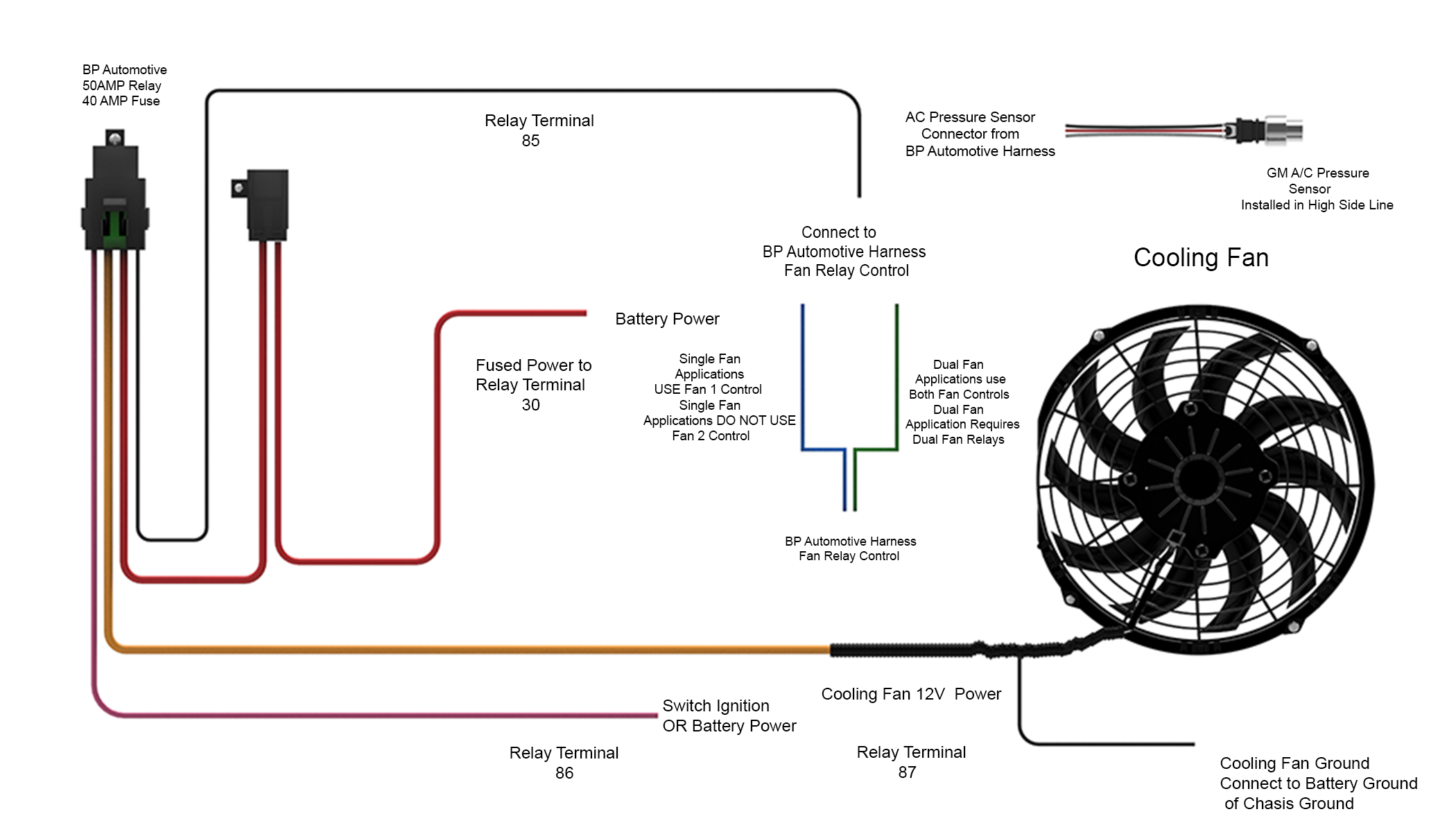
![[DIAGRAM] Automotive Cooling Fan Wiring Diagram FULL](https://www.griffinrad.com/images/website_graphics/single_fan.png)

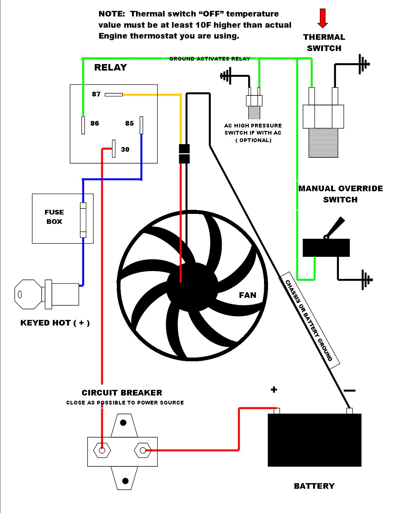
![[DIAGRAM] Automotive Cooling enthusiast Wiring Diagram FULL](https://lh3.googleusercontent.com/blogger_img_proxy/AEn0k_vJvZ6nHJQq5sTwxO13d7sW4T4eIjHBU4D4diGvDOJmrFvRUgWbcrMH_1oPIejfcksgqqbEn8hXJDs9MLlACweQVaqbxbQK9hG7UaMQYIcxhgi2o8R5-uJjm32UcGbphJbK=s0-d)


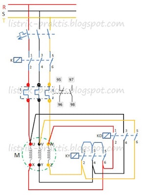
![[DIAGRAM] Wiring Diagram Panel Pompa Booster FULL Version](https://blogger.googleusercontent.com/img/b/R29vZ2xl/AVvXsEgNVftscl_U7B_at3n41dOwisBUf4A6652WjuFPaM1kcw4KVST_GpaJ4NOH_xKo2qoYhs3FYbIN5pFNgdE7hSrbnbtl6eBm6QsvBNNl36NzHLqMHqycmbPnunO_2MFjhEps-H1udA5ETkXB/s1600/gambar5.2.jpg)