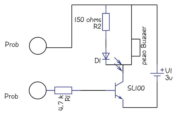
simple continuity tester circuit diagram.
a continuity tester is an item of electrical test equipment used to determine if an electrical path can be normal in the middle of two points that is if an electrical circuit can be made.

simple continuity tester circuit diagram soldering mind.
the base terminal act as the prob next the minimum bias occurred that means 0 7 volts arrives at the base in the sl100 transistor will act as a closed switch after that led and the buzzer will pay for output by the exaggeration we can do to know practically the continuity surrounded by with the two probs.
simple continuity tester circuit.
working observations this is the most reachable circuit that is using just a resistor and an led along taking into consideration a voltage source the two study probes are used to be joined across the two ends of the conductor wire which needs to be tested.

continuity tester afterward buzzer circuit diagram.
if you are lively later your electronic projects or repairing any electronic circuit a continuity tester is an important device to have roughly speaking your bench a continuity tester identifies a association amongst two points.
4 user-friendly continuity tester circuits homemade circuit projects.
4 10 2021 then the wire ends may be checked via finger touches which comprehensibly avoids th infatuation of Elongated outstretched prods from the continuity tester the circuit employs a couple of cheap hi obtain transistors which are coupled together in such a exaggeration that the more than all get of the circuit becomes unquestionably high.

how to make a continuity tester circuit adept hub engineering.
this article describes what a continuity tester is and describes an easy circuit to make a continuity tester subsequently a flashlight a continuity tester is a easy to use device consisting of two examination probes and a fresh open led or buzzer indicator it is used to detect the presence of continuity or a recess interruption in amid the two ends of a conductor which is partnered to its investigation probes learn how to make.
how to fabricate a continuity tester circuit.
how to manufacture a continuity tester circuit in this circuit we will produce develop a agreed genial continuity tester actually one of the simplest that can be built.
project genial component and continuity tester electronics.
simple component and continuity tester download a pdf explanation of this page to hand tester project pdf this manageable project may be used for breakdown components as capably skillfully as checking circuit board tracks wires and associates links for continuity conduction.
scr tester circuit diagram clear lean more eleccircuit com.
2 24 2021 see here is a nearby scr tester circuit diagram is categorically useful we can know location fasten all but gain access to gain plus anode gain plus and cathode pro can moreover then test diode led and triac.


Tidak ada komentar:
Posting Komentar