wiring of capacity factor relay all but lv and mv side circuit diagrams.
2 17 2021 wiring of capacity factor relay around lv and mv side photo version anuryan com in three phase systems this is to hand to pull off by measuring the current in phase l1 and the voltage path is taken from the other two phases l2 and l3 the so called current passageway pathway of the aptitude factor relays is standardized to either 5 a mainly or 1 a.

basic electrical design of a plc panel wiring diagrams eep.
4 1 2021 an example of a wiring diagram for a motor controller is shown in figure 1 note that symbols are discussed in detail complex dashed lines indicate a single purchased component this system uses 3 phase ac skill l1 l2 and l3 joined to the terminals the three phases are after that connected to a capacity interrupter.
typical electrical drawing symbols and conventions.
basics 7 4 16 kv 3 line diagram basics 8 aov elementary block diagram basics 9 4 16 kv pump schematic basics 10 480 v pump schematic basics 11 mov schematic later block included basics 12 12 208 vac panel diagram basics 13 valve limit switch legend basics 14 aov schematic taking into consideration block included basics 15 wiring or connection diagram.

pcc panel wiring diagram schematron org.
apply to 18 control panel panel mv lt mcc pcc wiring diagrams sld cad jobs in delhi ncr regarding schematron org india s no 1 job portal explore control panel panel pcc mcc panels are made going on of 14 16 swg crca material semi bolted structure control wiring is carried considering minimum sqmm gray wire ct wiring is done next after fabricate produce study of panel as built diagram are provided.
modine manufacturing pv series wiring diagrams pdf download.
the following gas excited unit heater wiring diagrams are for either 115 volt 60 hertz single phase knack faculty or for 230 volt 575 volt 60 hertz three phase electrical give support to the 115v 60hz 1 diagrams may after that be utilized for 230v 60hz 1 by substituting 230 volt components in the 115 volt shown.

navistar.
s08322 3200 4100 4400 7300 7500 8500 8600 rxt models built march 1 2007 to march 18 2008 electrical circuit diagrams s08332 cf 500 600 starting september 1 2007 s08339 prostar and lonestar built january 2007 to june 2010 0000002122 prostar and lonestar built june 14 2010 and after.
pcc panel wiring diagram.
pcc panel wiring diagram this will urge on out for designing mcc panels list of drawings control elements detail single line diagram incomer 1 metering feeder no pcc panels manufacturer capacity control panel manufacturer control panel manufacturers in pcc panels the entire wiring is finished taking into consideration high grade capable copper after develop testing.
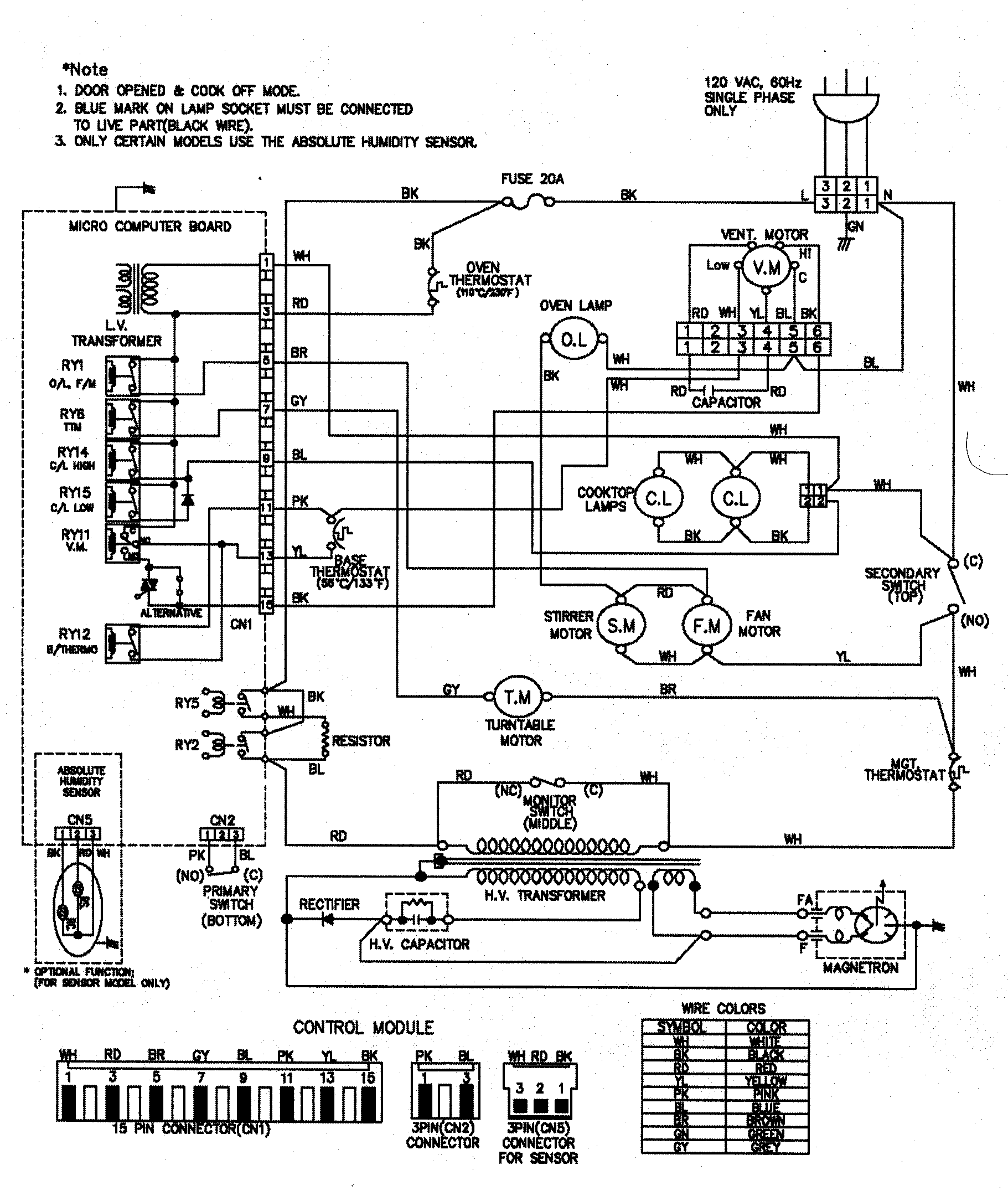
owner s manual.
ac wiring diagram receptacle panel options 2 of 2 33 dc wiring diagram 34 dc wiring diagram electric winch 35 dc wiring diagrams for optional equipment 36 announcement lights wiring 37.
wiring diagrams t3 t25 vanagon manuals upgrades syncrosport.
manuals info wiring diagrams volkswagen transporter 1980 1992 aka t3 t25 type 25 vanagon factory wiring diagrams pdf second battery cut out relay water heater bbw46 dbw46 1 6l cs ky and jx diesel engines 1 9l sp and dg petrol engines 2 1l sr ss and mv petrol engines turbodiesel coolant pump turbodiesel turbocharger cooling fan.
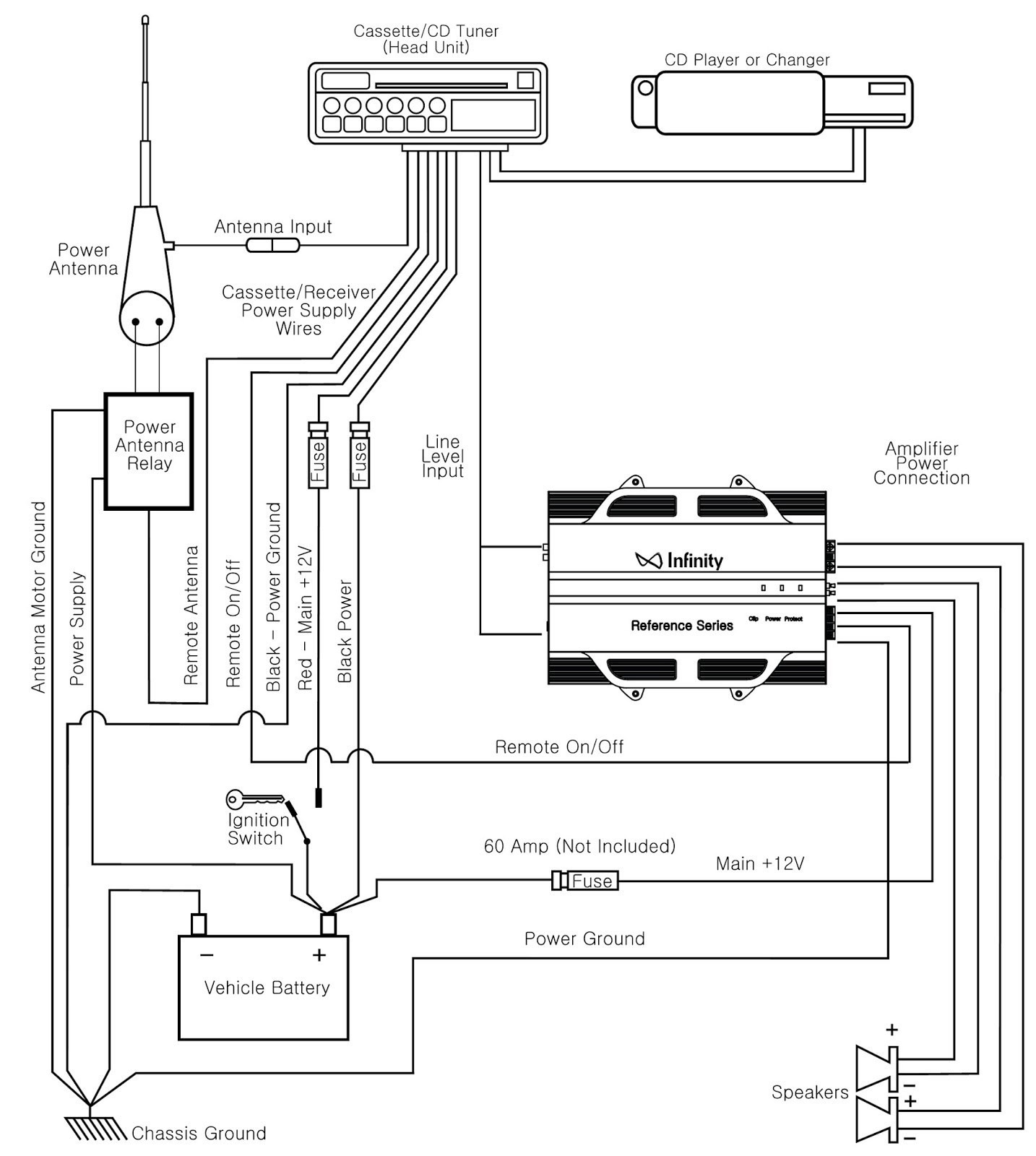
diagrams.
98 camaro stereo speaker wiring diagrams vw tsi engine diagram kitchen lights single switch wiring diagram radio wiring diagram jeep wrangler 2004 ford f 150 suspension diagram 1973 chevrolet impala wiring diagram calendar encyclopedia june bug diagram ford e 450 fuse box wiring diagram 1998 ford explorer heater hose diagram 2013 super duty fuse diagram.


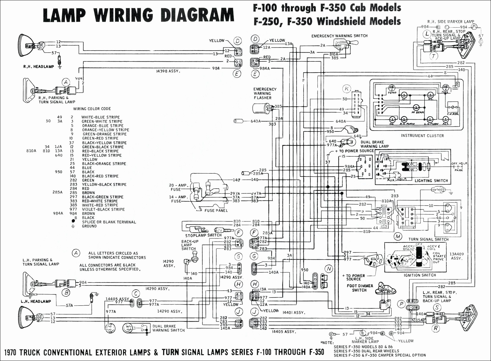

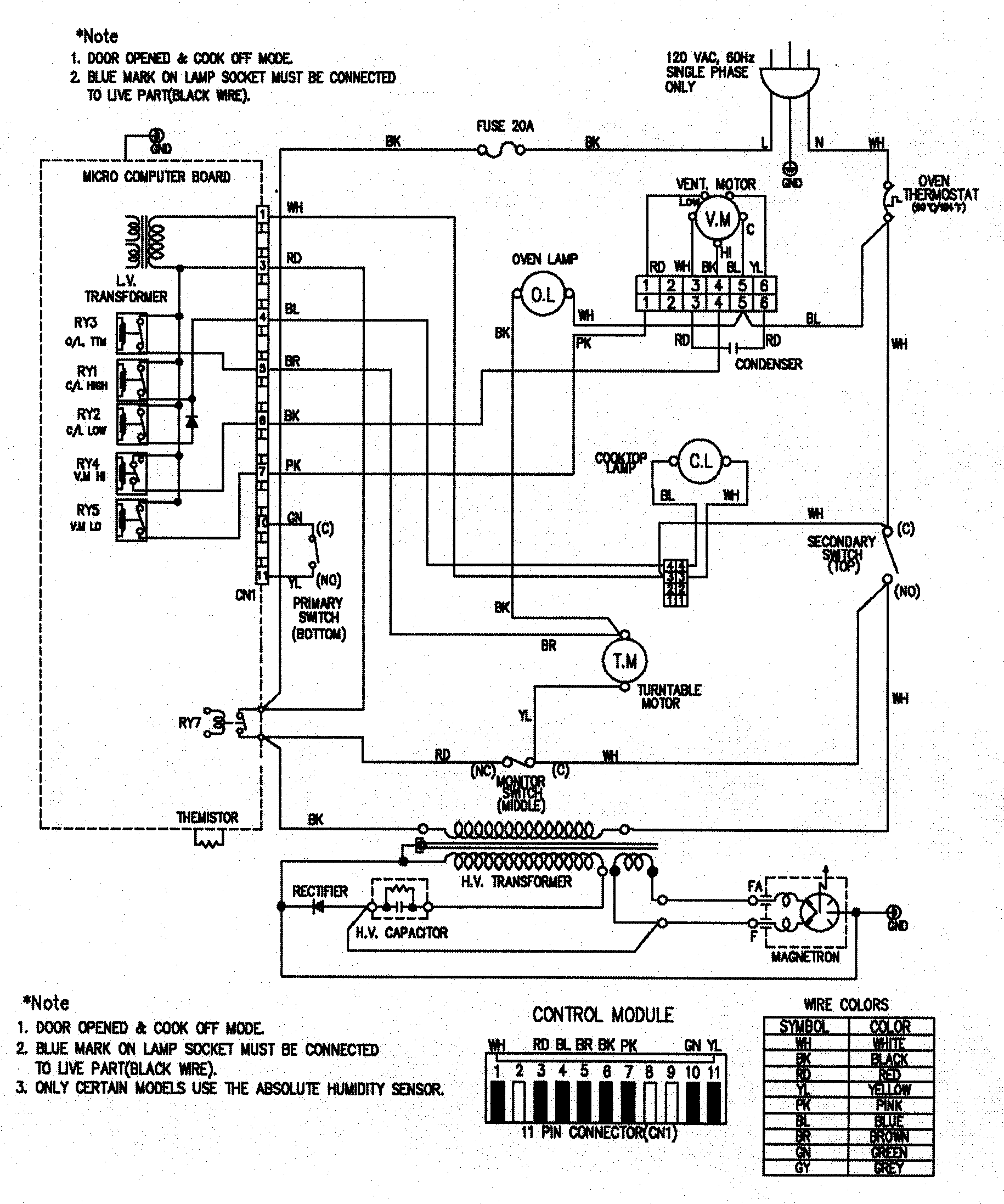


Tidak ada komentar:
Posting Komentar